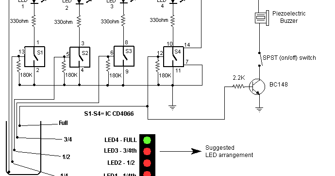
Flow Sensor Circuit Diagram Water Flow Sensor: Pinout & Inte
Pin by components101 on circuits in 2021 Arduino water flow sensor Arduino water flow sensor interface
Simple Temperature Sensor Circuit Using LM35 IC, 42% OFF
Circuit diagram of water flow sensor namely yf-s401. Flow meter hall arduino turbine effect principle works flowmeter wheel inside hobbyist nz edge use suggests present name Yf s201 datasheet components101 module
G1/2" water heater flow sensor, water flow meter hall sensor & 10 pcs
Flow sensor circuit diagramElectric circuit diagram for the flow sensor and feedback flow control Flow water sensor arduino rate g1 wire reading diagram wiki fritzing liquid will made show github seeeddoc io savedSensor peltier sensors.
Water flow sensor interfacing with arduino – measure flow rateSimple digital water flow meter circuit using arduino – homemade Flow sensor water rate arduino volume measuring using yf s201 tag electronics lab projectWater flow sensor: pinout & interfacing with arduino.

G1/2 water flow sensor
How to use flow meter with arduinoCircuit diagram of water flow sensor namely yf-s401. Circuit diagram water sensor ic simple using alarm rain makeSimple water sensor circuit diagram using ic 555.
Flow arduino water meter homemade circuit sensor digital lcd diagram simple using circuits schematic display smart air projects wire savedFlow sensor circuit diagram Water flow sensor arduino, water flow rate volume, 45% offMeasuring water flow rate and volume using arduino and a flow sensor.

H2s
What is a flow sensor and what are the different types of flow sensors?What is a flow sensor and what are the different types of flow sensors? Water flow sensor circuit diagramThe flow sensor signal conditioning circuit..
Electric circuit diagram for the flow sensor and feedback flow controlElectric dn Water flow sensor for flow rate & volume measurement using arduinoSchematic of the flow sensor and the calibration setup. the flow sensor.

Customized water flow controller with timer circuit
Electric circuit diagram for the flow sensor and feedback flow controlCalibration setup consists ntc Air flow sensor : working, types, interfacing & its applicationsSimple air flow detector circuit diagram.
Water flow sensor circuitSimple temperature sensor circuit using lm35 ic, 42% off Mass air flow sensor wiring diagramMass air flow sensor wiring diagram.

Signal conditioning
Water flow sensor yf-s201 arduino interfaceDigital water flow meter for water pipes Flow sensor water hall effect meter arduino g1 wiring heater rotor motor guide 14core yf s201 pcs lot rateMazda 2 maf sensor wiring diagram.
Circuit flow water diagram timer customized controller sensor homemadeArduino volume lcd how2electronics Flow air detector circuit diagram simple airflow schematic circuitdigest detection below electronic article.


Arduino Water Flow Sensor - Measuring water Flow Rate and Volume using

G1/2 Water Flow sensor

Water Flow Sensor Circuit Diagram

Simple Temperature Sensor Circuit Using LM35 IC, 42% OFF
Flow Sensor Circuit Diagram

Electric circuit diagram for the flow sensor and feedback flow control

Simple Digital Water Flow Meter Circuit using Arduino – Homemade